+7 (812) 929-8283
Cisco Aironet Antenna Reference Guide
Executive Overview
This antenna reference guide is intended to provide information to assist in understanding the issues and concerns of antennas used with a Cisco® Aironet® wireless LAN system, or wireless bridge system. It details deployment and design, limitations and capabilities, and basic theories of antennas. This document also contains information about the Cisco Systems® antennas and accessories, as well as installation scenarios, regulatory information, and technical specifications and diagrams of the available antennas.
Overview of Antennas
Each Cisco Aironet radio product is designed to perform in a variety of environments. Implementing the antenna system can greatly improve coverage and performance. To optimize the overall performance of a Cisco wireless LAN, it is important to understand how to maximize radio coverage with the appropriate antenna selection and placement. An antenna system comprises numerous components, including the antenna, mounting hardware, connectors, antenna cabling, and in some cases, a lightning arrestor.
Cisco partners can provide onsite engineering assistance for complex requirements.
Radio Technologies
In the mid-1980s, the U.S. Federal Communications Commission (FCC) modified Part 15 of the radio spectrum regulation, which governs unlicensed devices. The modification authorized wireless network products to operate in the Industrial, Scientific, and Medical (ISm bands using spread spectrum modulation. This type of modulation had formerly been classified and permitted only in military products. The ISM frequencies are in three different bands, located at 900 MHz,2.4 GHz, and 5 GHz. This document covers both the 2.4- and 5-GHz bands.
The ISM bands typically allow users to operate wireless products without requiring specific licenses, but this will vary in some countries. In the United States, there is no requirement for FCC licenses. The products themselves must meet certain requirements to be certified for sale, such as operation under 1-watt transmitter output power (in the United States) and maximum antenna gain or Effective Isotropic Radiated Power (EIRP) ratings.
The Cisco Aironet product lines utilize both the 2.4- and 5-GHz bands. In the United States, three bands are defined as unlicensed and known as the ISM bands. The ISM bands are as follows:
Each range has different characteristics. The lower frequencies exhibit better range, but with limited bandwidth and hence lower data rates. The higher frequencies have less range and are subject to greater attenuation from solid objects.
Direct Sequence Spread Spectrum
The Direct Sequence (DS) Spread Spectrum approach involves encoding redundant information into the RF signal. Every data bit is expanded toa string of chips called a chipping sequence or Barker sequence. The chipping rate as mandated by the U.S. FCC is 10 chips at the 1- and 2-Mbps rates and8 chips at the 11-Mbps rate. So, at 11 Mbps, 8 bits are transmitted for every one bit of data. The chipping sequence is transmitted in parallel across the spread spectrum frequency channel.
Frequency Hopping Spread Spectrum
Frequency Hopping (FH) Spread Spectrum uses a radio that moves or hops from one frequency to another at predetermined times and channels. The regulations require that the maximum time spent on any one channel is 400 milliseconds. For the 1- and 2-Mb FH systems, the hopping pattern must include75 different channels, and must use every channel before reusing any one. For the Wide Band Frequency Hopping (WBFH) systems, that permit up to 10-Mb data rates, the rules require use of at least 15 channels, and they cannot overlap. With only 83 MHz of spectrum, it limits the systems to 15 channels, thus causing scalability issues.
In every case, for the same transmitter power and antennas, a DS system will have greater range, scalability, and throughput than an FH system. For this reason Cisco has chosen to support only DS systems in the Spread Spectrum products.
Orthogonal Frequency Division Multiplexing
The Orthogonal Frequency Division Multiplexing (OFDm used in 802.11a and 802.11g data transmissions offers greater performance than the olderDS systems. In the OFDM system, each tone is orthogonal to the adjacent tones and therefore does not require the frequency guard band needed for DS. This guard band lowers the bandwidth efficiency and wastes up to 50 percent of the available bandwidth. Because OFDM is composed of many narrowband tones, narrowband interference degrades only a small portion of the signal with little or no effect on the remainder of the frequency components.
Antenna Properties and Ratings
An antenna gives the wireless system three fundamental properties-gain, direction, and polarization. Gain is a measure of increase in power. Direction is the shape of the transmission pattern. A good analogy for an antenna is the reflector in a flashlight. The reflector concentrates and intensifies the light beam in a particular direction similar to what a parabolic dish antenna would to a RF source in a radio system.
Antenna gain ratings are in decibels which is a ratio between two values. An antenna rating is typically to the gain of an isotropic or dipole antenna. An isotropic antenna is a theoretical antenna with a uniform three-dimensional radiation pattern (similar to a light bulb with no reflector). dBi is used to compare the power level of a given antenna to the theoretical isotropic antenna. The U.S. FCC uses dBi in its calculations. An isotropic antenna is said to have a power rating of 0 dB; for example, zero gain/loss when compared to itself.
Unlike isotropic antennas, dipole antennas are real antennas (dipole antennas are standard on Cisco Aironet access points, base stations, and workgroup bridges). Dipole antennas have a different radiation pattern compared to isotropic antennas. The dipole radiation pattern is 360 degrees in the horizontal plane and 75 degrees in the vertical plane (assuming the dipole antenna is standing vertically) and resembles a donut in shape. Because the beam is "slightly" concentrated, dipole antennas have a gain over isotropic antennas of 2.14dB in the horizontal plane. Dipole antennas are said to have a gain of 2.14 dBi (in comparison to an isotropic antenna).
Some antennas are rated in comparison to dipole antennas. This is denoted by the suffix dBd. Hence, dipole antennas have a gain of 0 dBd(= 2.14 dBi).
Note that the majority of documentation refers to dipole antennas as having a gain of 2.2 dBi. The actual figure is 2.14 dBi, but is often rounded up.
TYPE OF ANTENNAS
Cisco offers several different styles of antennas for use with both access points and bridges in the 2.4 GHz product line, as well as the 5 GHzBR1400 bridge. Every antenna offered for sale has been FCC-approved. Each type of antenna will offer different coverage capabilities. As the gain of an antennaincreases, there is some tradeoff to its coverage area. Usually gain antennas offer longer coverage distances, but only in a certain direction. The radiation patternsbelow will help to show the coverage areas of the styles of antennas that Cisco offers: omnidirectional, yagis, and patch antennas.
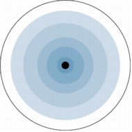
Omnidirectional Antennastional antenna (Figure 1) is designed to provide a 360-degree radiation pattern. This type of antenna is used when coverage in all directionsfrom the antenna is required. The standard 2.14 dBi "Rubber Duck" is one style of omnidirectional antenna.
Figure 1. Omnidirectional Antenna
Directional Antennas
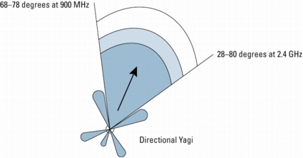
Directional antennas come in many different styles and shapes. An antenna does not offer any added power to the signal; it simply redirects theenergy it receives from the transmitter. By redirecting this energy, it has the effect of providing more energy in one direction, and less energy in all otherdirections. As the gain of a directional antenna increases, the angle of radiation usually decreases, providing a greater coverage distance, but with a reducedcoverage angle. Directional antennas include yagi antennas (Figure 3), patch antennas (Figure 2), and parabolic dishes. Parabolic dishes have a very narrow RF energypath and the installer must be accurate in aiming these at each other.
Figure 2. Directional Patch Antenna
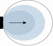
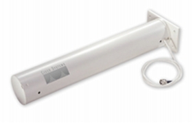
Figure 3. YAGI Antenna
Diversity Antenna Systems
Diversity antenna systems are used to overcome a phenomenon known as multipath distortion of multipath fading. It uses two identical antennas, located a small distance apart, to provide coverage to the same physical area.
Multipath Distortion
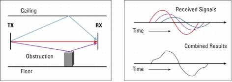
Multipath interference occurs when an RF signal has more than one path between a receiver and a transmitter. This occurs in sites that havea large amount of metallic or other RF reflective surfaces.
Just as light and sound bounce off of objects, so does RF. This means there can be more than one path that RF takes when going from a TX to and RX antenna.These multiple signals combine in the RX antenna and receiver to cause distortion of the signal.
Multipath interference can cause the RF energy of an antenna to be very high, but the data would be unrecoverable. Changing the type of antenna,and location of the antenna can eliminate multipath interference (Figure 4).
Figure 4. Multipath Distortion
You can relate this to a common occurrence in your car. As you pull up to a stop, you may notice static on the radio. But as you move forward a few inchesor feet, the station starts to come in more clearly. By rolling forward, you move the antenna slightly, out of the point where the multiple signals converge.
A diversity antenna system can be compared to a switch that selects one antenna or another, never both at the same time. The radio in receive mode willcontinually switch between antennas listening for a valid radio packet. After the beginning sync of a valid packet is heard, the radio will evaluate the syncsignal of the packet on one antenna, then switch to the other antenna and evaluate. Then the radio will select the best antenna and use only that antenna forthe remaining portion of that packet.
On transmit, the radio will select the same antenna it used the last time it communicated to that given radio. If a packet fails, it will switch to the otherantenna and retry the packet.
One caution with diversity, it is not designed for using two antennas covering two different coverage cells. The problem in using it this wayis that, if antenna no. 1 is communicating to device no. 1 while device no. 2 (which is in the antenna no. 2 cell) tries to communicate, antenna no.2 is not connected (due to the position of the switch), and the communication fails. Diversity antennas should cover the same area from only a slightly differentlocation.
With the introduction of the latest DS physical layer chips, and the use of diversity antenna systems, DS systems have equaled or surpassed FH in handlingmultipath interference. While the introduction of WBFH does increase the bandwidth of FH systems, it drastically affects the ability to handle multipathissues, further reducing its range compared to present DS systems in high RF reflective sites.
WIRELESS LAN DESIGN
Before the physical environment is examined, it is critical to identify the mobility of the application, the means for coverage, and systemredundancy. An application such as point-to-point, which connects two or more stationary users, may be best served by a directional antenna, while mobileusers will generally require a number of omnidirectional micro cells. These individual micro cells can be linked together through the wired LAN infrastructureor by using the wireless repeater functionality built into every Cisco Aironet Access Point. All Cisco Aironet Wireless LAN products are designed to support complexmulticell environments transparently through the patented Cisco MicroCellular Architecture.
THE PHYSICAL ENVIRONMENT
After mobility issues are resolved, the physical environment must be examined. While the area of coverage is the most important determining factorfor antenna selection, it is not the sole decision criteria. Building construction, ceiling height, internal obstructions, available mounting locations, and customeraesthetic desires also must be considered. Cement and steel construction have different radio propagation characteristics. Internal obstructions such as product inventoryand racking in warehousing environments are factors. In outdoor environments, many objects can affect antenna patterns, such as trees, vehicles, and buildings, to namea few.
The Network Connections
The access points use a 10/100-Mb Ethernet connection. Typically the access point is in the same location as the antenna. While it may seemthat the best place to put the access point is in a wiring closet with the other network components, such as switches, hubs, and routers, this is not thecase. The antenna must be placed in an area that provides the best coverage (determined by a site survey). Many people new to wireless LANs want to locate theaccess points in the wiring closet and connect the antenna using RF coax. Antenna cable introduces losses in the antenna system on both the transmitter and thereceiver. As the length of cable increases, so does the amount of loss introduced. To operate at optimum efficiency, cable runs should be kept as short as possible.(See the section on cabling later in this document).
Building Construction
The density of the materials used in a building's construction determines the number of walls the RF signal can pass through and still maintainadequate coverage. Following are a few examples. Actual effect on the RF must be tested at the site, and therefore a site survey is suggested.
Paper and vinyl walls have very little effect on signal penetration. Solid walls and floors and precast concrete walls can limit signal penetrationto one or two walls without degrading coverage. This may vary widely based on any steel reinforcing within the concrete. Concrete and concrete block walls maylimit signal penetration to three or four walls. Wood or drywall typically allow for adequate penetration through five or six walls. A thick metal wall reflects signals,resulting in poor penetration. Steel-reinforced concrete flooring will restrict coverage between floors to perhaps one or two floors.
Recommendations for some common installation environments are outlined below:
- Warehousing/Manufacturing-In most cases, these installations require a large coverage area. Experience has shown that an omnidirectional antenna mounted at 20 to 25 feet typically provides the best overall coverage. Of course, this also depends upon the height of the racking, material on the rack, and ability to locate the antenna at this height. Mounting the antenna higher will sometimes actually reduce coverage, as the angle of radiation from the antenna is more outward than down. The antenna should be placed in the center of the desired coverage cell and in an open area for best performance. In cases where the radio unit will be located against a wall, a directional antenna such as a patch or yagi can be used for better penetration of the area. The coverage angle of the antenna will affect the coverage area.
- Small Office/Small Retail-The standard dipole may provide adequate coverage in these areas depending on the location of the radio device. However, in a back corner office a patch antenna may provide better coverage. It can be mounted to the wall above most obstructions for best performance. Coverage of this type antenna depends on the surrounding environment.
- Enterprise/Large Retail-In most cases, these installations require a large coverage area. Experience has shown that omnidirectionalantennas mounted just below the ceiling girders or just below the drop ceiling typically provide the best coverage (this will vary with stocking, type of material, and building construction). The antenna should be placed in the center of the desired coverage cell and in an open area for best performance. In cases where the radio unit will be located in a corner, or at one end of the building, a directional antenna such as a patch or yagi can be used for better penetration of the area. Also, for areas that are long and narrow-such as long rows of racking-a directional antenna at one end may provide better coverage. The radiation angle of the antennas will also affect the coverage area.
- Point-to-Point-When connecting two points together (such as a wireless bridge), the distance, obstructions, and antenna location must be considered. If the antennas can be mounted indoors and the distance is very short (several hundred feet), the standard dipole or mast mount 5.2 dBi omnidirectional may be used. An alternative is to use two patch antennas. For very long distances (1/2 mi. or more), directional high-gain antennas must be used. These antennas should be installed as high as possible, and above obstructions such as trees, buildings, and so on; and if directional antennas are used, they must be aligned so that their main radiated power lobes are directed at each other. With a line-of-site configuration, distances of up to 25 miles at 2.4 GHz and 12 miles at 5 GHz can be reached using parabolic dish antennas, if a clear line-of-site is maintained. With the use of directional antennas, fewer interference possibilities exist and there is less possibility of causing interference to anyone else.
- Point-to-Multipoint Bridge-In this case (in which a single point is communicating to several remote points), the use of an omnidirectional antenna at the main communication point must be considered. The remote sites can use a directional antenna that is directed at the main point antenna.
CABLING
As stated above, cabling introduces losses into the system, negating some of the gain an antenna introduces and reducing range of the RF coverage.
Interconnect Cable
Attached to all antennas (except the standard dipoles), this cable provides a 50 Ohm impedance to the radio and antenna, with a flexible connection between the two items. It has a high loss factor and should not be used except for very short connections (usually less than 10 feet). Typical length on all antennas is 36 in. (or 12 in. on some outdoor antennas).
Low-Loss/Ultra-Low-Loss Cable
Cisco offers two styles of cables for use with the 2.4 GHz and 5 GHz product line. These cables provide a much lower loss factor than standard interconnect cable, and they can be used when the antenna must be placed at any distance from the radio device. While these are low-loss cables, they should still be kept to a minimum length. There are two types of cable supplied by Cisco for mounting the antenna away from the radio unit. The 100 and 150 foot cables are LMR600 type cable, while the 20 and 50 foot cables are LMR400 type cables. All four lengths are supplied with one RP-TNC plug and one RP-TNC jack connector attached. This allows for connection to the radio unit and to the interconnect cable supplied on the antennas.
Connectors
According to the US Federal Code of Regulations, products used in the 2.4 and 5 GHz ISM bands manufactured after June 1994 must either use connectors that are unique, and nonstandard (meaning not readily available on the market by the average user) or be designed to be professionally installed (professional here indicates a person trained in RF installation and regulations). Since many of the 2.4 GHz products are installed by non-RF trained personnel, these products must comply with the unique connector ruling. The BR1400 is designed for installation by a RF professional, and therefore may use a standard `N' style connector. Cisco Aironet 2.4 GHz products use Reverse Polarity -TNC (RP-TNC) connectors. While they are similar to the normal TNC connectors, they cannot be mated to the standard connectors. To ensure compatibility with Cisco Aironet products, use antennas and cabling from Cisco.
MOUNTING HARDWARE
Each antenna requires some type of mounting. The standard dipole antenna simply connects to the RP-TNC connector on the back of the unit. Mast mount antennas are designed to mount to a mast up to 1.5 inches, and each comes with mounting hardware for attachment. The Yagi antennas have an articulating mount option, which is included in the back of this document. Patch antennas are designed to mount flat against a wall or ceiling, and ceiling-mount antennas are equipped with a drop-ceiling cross-member attachment. The 2.4 GHz 21 dBi parabolic dish mounts to a 1.625- to a 2.375-in. mast and fine-threaded turnbuckles allow accurate aiming of the antenna. All the BR1400 external 5 GHz antennas can be attached to a mast ranging from 1.5 to 2.5 inches.
For most indoor applications, a .75- or 1-in. electrical conduit provides a suitable mounting. For outdoor application, a heavy galvanized or aluminum wall mast should be used that will withstand the wind-loading rating of the selected antenna.
LIGHTNING ARRESTORS
When using outdoor antenna installations, it is always possible that an antenna will suffer damage from potential charges developing on the antenna and cable, or surges induced from nearby lightning strikes. The BR1400 includes lightning protection at the power injector, while the Aironet lightning arrestor is designed to protect 2.4 GHz to 5.8 GHz radio equipment from static electricity and lightning-induced surges that travel on coaxial transmission lines. Both systems need to be properly grounded as identified in the hardware installation manuals of the products. These protection mechanisms will not prevent damage in the event of a direct lightning hit.
Theory of Operation
The Cisco Aironet Lightning Arrestor (Figure 5) prevents energy surges from reaching the RF equipment by the shunting effect of the device. Surges are limited to less than 50 volts, in about .0000001 seconds (100 nano seconds). A typical lightning surge is about .000002 (2 micro seconds).
Figure 5. Cisco Aironet Lightning Arrestor
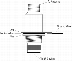
The accepted IEEE transient (surge) suppression is .000008 seconds (8 micro seconds). The Lightning Arrestor is a 50-ohm transmission line with a gas discharge tube positioned between the center conductor and ground. This gas discharge tube changes from an open circuit to a short circuit almost instantaneously in the presence of voltage and energy surges, providing a path to ground for the energy surge.
Installation
This arrestor is designed to be installed between your outdoor antenna cable and the Aironet wireless device. Installation should be indoors, or inside a protected area. A good ground must be attached to the arrestor. This can be accomplished by use of a ground lug attached to the arrestor and a heavy wire (no. 6 solid copper) connecting the lug to a good earth ground. See Figure 6.
UNDERSTANDING RF POWER VALUES
Radio frequency (RF) signals are subject to various losses and gains as they pass from transmitter through cable to antenna, through air (or solid obstruction), to receiving antenna, cable, and receiving radio. With the exception of solid obstructions, most of these figures and factors are known and can be used in the design process to determine whether an RF system such as a WLAN will work.
Decibels
The decibel (dB) scale is a logarithmic scale used to denote the ratio of one power value to another-for example:
dB = 10 log10 (Power A/Power B)
An increase of 3 dB indicates a doubling (2x) of power. An increase of 6 dB indicates a quadrupling (4x) of power. Conversely, a decrease of 3 dB is a halving (1/2) of power, and a decrease of 6 dB is a quarter (1/4) the power. Some examples are shown below in Table 1.
Table 1. Decibel Values and Corresponding Factors
| Increase | Factor | Decrease | Factor |
|---|---|---|---|
| 0 dB | 1 x (same) | 0 dB | 1 x (same) |
| 1 dB | 1.25 x | -1 dB | 0.8 x |
| 3 dB | 2 x | -3 dB | 0.5 x |
| 6 dB | 4 x | -6 dB | 0.25 x |
| 10 dB | 10 x | -10 dB | 0.10 x |
| 12 dB | 16 x | -12 dB | 0.06 x |
| 20 dB | 100 x | -20 dB | 0.01 x |
| 30 dB | 1000 x | -30 dB | 0.001 x |
| 40 dB | 10,000 x | -40 dB | 0.0001 x |
POWER RATINGS
WLAN equipment is usually specified in decibels compared to known values. Transmit Power and Receive Sensitivity are specified in "dBm," where "m" means 1 milliWatt (mW). So, 0 dBm is equal to 1 mW; 3 dBm is equal to 2 mW; 6 dBm is equal to 4 mW, and so on.
Table 2. Common mW Values to dBm Values
| dBm | mW | dBm | mW |
|---|---|---|---|
| 0 dBm | 1 mW | 0 dBm | 1 mW |
| 1 dBm | 1.25 mW | -1 dBm | 0.8 mW |
| 3 dBm | 2 mW | -3 dBm | 0.5 mW |
| 6 dBm | 4 mW | -6 dBm | 0.25 mW |
| 7 dBm | 5 mW | -7 dBm | 0.20 mW |
| 10 dBm | 10 mW | -10 dBm | 0.10 mW |
| 12 dBm | 16 mW | -12 dBm | 0.06 mW |
| 13 dBm | 20 mW | -13 dBm | 0.05 mW |
| 15 dBm | 32 mW | -15 dBm | 0.03 mW |
| 17 dBm | 50 mW | -17 dBm | 0.02 mw |
| 20 dBm | 100 mW | -20 dBm | 0.01 mW |
| 30 dBm | 1000 mW (1 W) | -30 dBm | 0.001 mW |
| 40 dBm | 10,000 mW (10 W) | -40 dBm | 0.0001 mW |
Outdoor Range
The range of a wireless link is dependent upon the maximum allowable path loss. For outdoor links this is a straightforward calculation as long as there is clear line of sight between the two antennas with sufficient clearance for the Fresnel zone. For line of sight, you should be able to visibly see the remote locations antenna from the main site. (Longer distances may require the use of binoculars). There should be no obstructions between the antennas themselves. This includes trees, buildings, hills, and so on.
As the distance extends beyond six miles, the curve of the earth (commonly called earth bulge) affects installation, requiring antennas to be placed at higher elevations.
Fresnel Zone
Fresnel zone is an elliptical area immediately surrounding the visual path. It varies depending on the length of the signal path and the frequency of the signal. The Fresnel zone can be calculated, and it must be taken into account when designing a wireless link (Figure 6).
Figure 6. Fresnel Zone
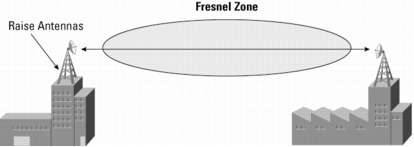
Based on both line-of-sight and Fresnel zone requirements, Table 3 provides a guideline on height requirements for 2.4 GHz antennas as various distances. This refers to height above any obstacles located in the middle of the RF path.
Table 3. Guideline on Height Requirements for 2.4 GHz Antennas
| Wireless Link Distance (miles) | Approx. Value "F" (60% Fresnel Zone) Ft. at 2.4 GHz | Approx. Value "C" (Earth Curvature) | Value "H" (mounting Ht.) Ft. with No Obstructions |
|---|---|---|---|
| 1 | 10 | 3 | 13 |
| 5 | 30 | 5 | 35 |
| 10 | 44 | 13 | 57 |
| 15 | 55 | 28 | 83 |
| 20 | 65 | 50 | 115 |
| 25 | 72 | 78 | 150 |
Cisco.com provides an Outdoor Bridge Range Calculation Utility for both the 2.4GHz and 5 GHz products. This utility calculates the Fresnel zone and maximumrange based upon cable types and lengths, transmitter and receiver models, and antennas.
A 10 dB fade margin is included for 2.4 GHz calculations, while the included 5dB fade margin for 5 GHz calculations is sufficient for dependable communications in all weather conditions. The distances given are only theoretical and should only be used to determine the feasibility of a particular design.
Outdoors, every increase of 6 dB will double the distance. Every decrease of 6 dB will halve the distance. Shorter cable runs and higher gain antennas can make a significant difference to the range.
REGULATIONS
North America
• Connectors-In 1985, the FCC enacted standards for the commercial use of spread spectrum technology in the ISM frequency bands. Spread spectrum is currently allowed in the 900, 2400, and 5200 MHz bands. In 1989, the FCC drafted an amendment governing spread spectrum systems in the unlicensed ISM band. This amendment is commonly referred to as the "new" or "'94" rules because it impacts all spread spectrum products manufactured after June 23, 1994. Products manufactured before June 23 are not affected by the amendment. Congress enacted this amendment into law in 1990. The FCC 1994 rules are intended to discourage use of amplifiers, high-gain antennas, or other means of significantly increasing RF radiation. The rules are further intended to discourage "home brew" systems which are installed by inexperienced users and which-either accidentally or intentionally-do not comply with FCC regulations for use in the ISM band. Both the original rules and the amendments sought to enable multiple RF networks to "coexist" with minimum impact on one another by exploiting properties of spread spectrum technology. Fundamentally, the FCC 1994 rules intend to limit RF communications in the ISM band to a well-defined region, while ensuring multiple systems can operate with minimum impact on one another. These two needs are addressed by limiting the type and gain of antennas used with a given system, and by requiring a greater degree of RF energy "spreading."
The FCC limits the use of the lower four channels (the UNII-1 band) of the 5-GHz band, requiring antennas that are permanently attached to the transmitting device. Due to this, Cisco offers an articulating antenna paddle with omnidirectional and patch antennas on the 802.11a access point radio module to extend the flexibility of deployments. For ceiling, desktop, or other horizontal installations, the omnidirectional antenna provides optimal coverage pattern and maximum range. For wall mount installations, the patch antenna provides a hemispherical coverage pattern that uniformly directs the radio energy from the wall and across the room. In omni mode, the antenna gain is 5 dBi with a 360-degree radiation pattern; in patch mode, the gain is 6 dBi with a 180-degree pattern. Both the omnidirectional and patch antennas provide diversity for maximum reliability, even in high multi-path environments like offices.
• Antenna Gain and Power Output-FCC regulations specify maximum power output and antenna gain. For the UNII3 band, where the BR1400 operates, the FCC limits the transmitter power to 1 watt or 30dBm, and the antenna gain of an omni directional antenna to 6 dBi. For directional antennas operating in a point to point system, gains of up to 23 dBi are permitted. For antennas with gain higher than 23 dBi, the transmitter output power must be reduced 1 dB for every 1 dB above 23 dBi the antenna gain increases.
At 2.4 GHz, the maximum transmitter power is also 1 watt. Using this maximum power, the maximum antenna gain is 6 dBi. However, the regulations also define the maximum values in regards to the following two different system scenarios:
In point-to-multipoint systems, the FCC has limited the maximum EIRP (effective isotropic radiated power) to 36 dBm. EIRP = TX power + antenna gain. For every dB that the transmitter power is reduced, the antenna may be increased by 1 dB. (29 dBm TX, +7 dB antenna = 36 dBm EIRP, 28 dBm TX, +8 dB antenna = 36 dBm EIRP).
The Cisco Aironet 2.4 GHz Bridge transmitter power is 20 dBm, which is 10 dBm lower than maximum. This then allows the use of antennas up to 10 dB over the initial 6 dBi limit, or 16 dBi.
In point-to-point systems for 2.4 GHz systems using directional antennas, the rules have changed. Because a high gain antenna has a narrow beamwidth, the likelihood is high that it will cause interference to other area users. Under the rule change, for every dB the transmitter is reduced below 30 dBm the antenna may be increased from the initial 6 dBi, by 3 dB. (29 dB transmitter means 9 dBi antenna, 28 dB transmitter means 12 dBi antenna). Because we are operating at 20 dBm, which is 10 dB below the 30 dBm level, we can increase the out antenna by 30 dB. Note that Cisco has never tested, and therefore is not certified, with any antenna larger than 21 dBi.
The main issue that comes to question here is, what differentiates a point-to-point from a multipoint system.
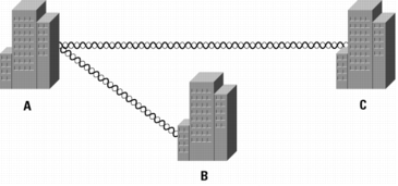
In Figure 7, point A communicates to a single point, B, and point B communicates to a single point A; therefore, it is simple to see that both locations see this as a point-to-point installation.
In Figure 8, point A communicates to more than one (or multiple) points; therefore, point A is operating in a multipoint configuration, and the largest antenna permitted is 16 dBi. Point B or point C can each communicate to only one point, (point A); therefore, point B and point C actually operate in a single-point or point-to-point operation, and a larger antenna may be used.
Figure 7. Point-to-Point Wireless Bridge Solution

Figure 8. Point-to-Multipoint Wireless Bridge Solution
• Amplifiers-The FCC Rules, Section 15.204-Part C, states "External radio frequency power amplifiers shall not be marketed as separate products..." Part D states "Only the antenna with which an intentional radiator (transmitter) is originally authorized may be used with the intentional radiator." This means that unless the amplifier manufacturer submits the amplifier for testing with the radio and antenna, it cannot be sold in the U.S. If it has been certified, then it must be marketed and sold as a complete system, including transmitter, antenna, and coax. It also must be installed exactly this way.
If using a system that includes an amplifier, remember that the above rules concerning power are still in effect. If the amplifier is 1/2 watt (27 dBm, this means in a multipoint system the maximum antenna gain is only 9 dBi, and in a point-to-point system it is only 15 dBi.
ETSI
The European Telecommunication Standardization Institute (ETSI) has developed standards that have been adopted by many European countries as well as many others. Under the ETSI regulations, the power output and EIRP regulations are much different than in the U.S.
• Antenna Gain and Power Output-The ETSI regulations specify maximum EIRP as 20 dBm. Since this includes antenna gain, this limits the antennas that can be used with a transmitter. To use a larger antenna, the transmitter power must be reduced so that the overall gain of the transmitter, plus the antenna gain, less any losses in coax, is equal to or less than +20 dBm. This drastically reduces the overall distance an outdoor link can operate.
• Amplifiers-Since the ETSI regulation has such a low EIRP, the use of amplifiers is typically not permitted in any ETSI system.
FREQUENCIES AND CHANNEL SETS
IEEE 802.11b/g Direct Sequence Channels
Fourteen channels are defined in the IEEE 802.11b/g Direct Sequence (DS) channel set. Each DS channel as transmitted is 22 MHz wide; however, the channel center separation is only 5 MHz. This leads to channel overlap such that signals from neighboring channels can interfere with each other. In a 14-channel DS system (11 usable in the US), only three non-overlapping (and hence, non-interfering channels, 25 MHz apart, are possible (for example, channels 1, 6, and 11).
This channel spacing governs the use and allocation of channels in a multi-access point environment such as an office or campus. Access points are usually deployed in "cellular" fashion within an enterprise where adjacent access points are allocated non-overlapping channels. Alternatively, access points can be collocated using channels 1, 6, and 11 to deliver 33 Mbps bandwidth to a single area (but only 11 Mbps to a single client). The channel allocation scheme is illustrated in Figure 9, and the available channels in the different regulatory domains are defined in Table 4 on the following page.
Figure 9. IEEE 802.11b/g DSSS Channel Allocations

Table 4 exhibits the channels permitted in the corresponding approval areas.
Table 4. DSSS PHY Frequency Channel Plan
| Channel ID | Frequency (MHz) | Regulatory Domains (Maximum Conducted Average Power Levels in dBm | |||||||||||||||||||
|---|---|---|---|---|---|---|---|---|---|---|---|---|---|---|---|---|---|---|---|---|---|
| -A | -C | -E | -I | -J | -K | -N | -P | -S | -T | ||||||||||||
| 2400-2484 MHz | |||||||||||||||||||||
| Mode | B | G | B | G | B | G | B | G | B | G | B | G | B | G | B | G | B | G | B | G | |
| 1 | 2412 | X | X | X | X | X | X | X | X | X | X | X | X | X | X | X | X | X | X | ||
| 2 | 2417 | X | X | X | X | X | X | X | X | X | X | X | X | X | X | X | X | X | X | ||
| 3 | 2422 | X | X | X | X | X | X | X | X | X | X | X | X | X | X | X | X | X | X | ||
| 4 | 2427 | X | X | X | X | X | X | X | X | X | X | X | X | X | X | X | X | X | X | ||
| 5 | 2432 | X | X | X | X | X | X | X | X | X | X | X | X | X | 17 | X | X | X | X | X | X |
| 6 | 2437 | X | X | X | X | X | X | X | X | X | X | X | X | X | X | X | X | X | X | X | X |
| 7 | 2442 | X | X | X | X | X | X | X | X | X | X | X | X | X | X | X | X | X | X | X | X |
| 8 | 2447 | X | X | X | X | X | X | X | X | X | X | X | X | X | X | X | X | X | X | X | X |
| 9 | 2452 | X | X | X | X | X | X | X | X | X | X | X | X | X | X | X | X | X | X | X | 17 |
| 10 | 2457 | X | X | X | X | X | X | X | X | X | X | X | X | X | X | X | X | X | X | X | X |
| 11 | 2462 | X | X | X | X | X | X | X | X | X | X | X | X | X | X | X | X | X | X | X | X |
| 12 | 2467 | X | X | X | X | X | X | X | X | X | X | X | X | X | X | ||||||
| 13 | 2472 | X | X | X | X | X | X | X | X | X | X | X | X | X | X | ||||||
| 14 | 2484 | X | X | ||||||||||||||||||
IEEE 802.11a Channels
The 802.11a specification today specifies 4 channels for the UNII1 band, 4 channels for the UNII@ band, and 4 channels for the UNII3 band. These channels are spaced at 20 MHz apart and are considered non-interfering, however they do have a slight overlap in frequency spectrum. It is possible to use adjacent channels in adjacent cell coverage, but it is recommended when possible to separate adjacent cell channels by at least 1 channel. Figure 10 shows the channel scheme for the 802.11 bands, and table 9 lists the North American frequency allocations.
Figure 10. 802.11a Channel Allocation
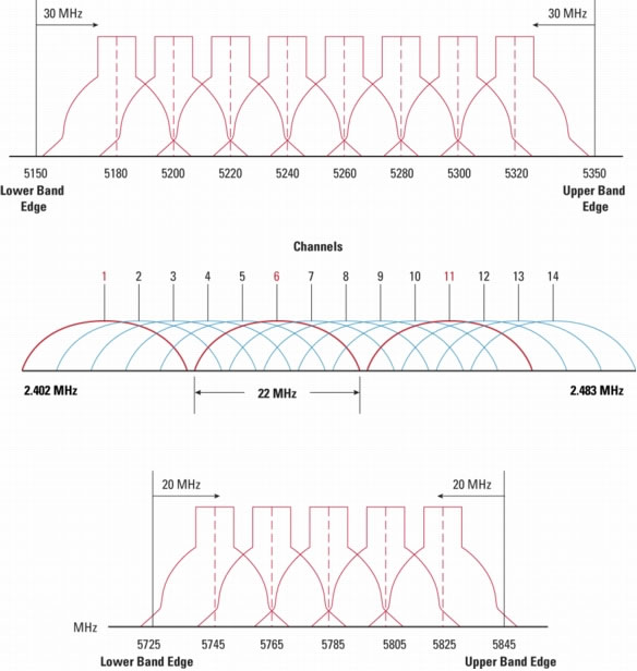
Table 5. 802.11a Frequency Plan
| Regulatory Domain | Frequency Band | Channel Number | Centre Frequencies |
|---|---|---|---|
| USA | UNII lower band5.15-5.25 GHz | 36 | 5.180 GHz |
| 40 | 5.220 GHz | ||
| 44 | 5.230 GHz | ||
| 48 | 5.240 GHz | ||
| USA | UNII middle band5.25-5.35 GHz | 52 | 5.260 GHz |
| 56 | 5.280 GHz | ||
| 60 | 5.300 GHz | ||
| 64 | 5.320 GHz | ||
| USA | UNII upper band5.725-5.825 GHz | 149 | 5.745 GHz |
| 153 | 5.795 GHz | ||
| 157 | 5.785 GHz | ||
| 161 | 5.805 GHz | ||
| USA | ISM band5.725-5.825 GHz | 149 | 5.745 GHz |
| 153 | 5.795 GHz | ||
| 157 | 5.785 GHz | ||
| 161 | 5.805 GHz | ||
| 165 | 5.825 GHz |
CISCO AIRONET ANTENNA DESCRIPTIONS
Table 6 below defines the various 2.4 GHz antennas that are offered by Cisco for the Cisco Aironet product line, and Table 7 lists the available antennas for the Cisco Aironet 5 GHz bridge products.
Table 6. 2.4 GHz Antennas
| Cisco Part Number | Antenna Type | Description | Gain |
|---|---|---|---|
| AIR-ANT5959 | Diversity Omnidirectional | Ceiling-mount diversity indoor antenna with RP-TNC connectors-This antenna was designed for WLAN applications for frequencies of 2400-2500 MHz. The antenna is omnidirectional and has a nominal gain of 2.2 dBi. Its low profile allows it to remain unnoticed in the ceiling. It comes with a clip that permits it to be mounted to a drop-ceiling cross member. | |
| AIR-ANT3351 | Diversity Omnidirectional | POS diversity dipoles for use with LMC radio cards with two MMCX connectors-This antenna contains two standard 2.2 dBi dipoles and 59" of cable terminating in two MMCX connectors. It has a platform with an adhesive backing to raise the antennas above obstructions. | 2.2 dBi |
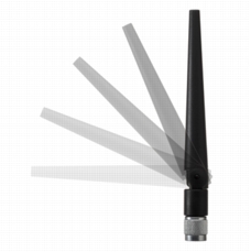
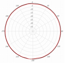
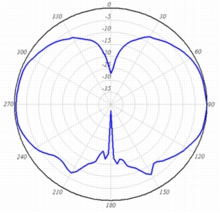
| AIR-ANT4941 | Omnidirectional | Single black dipole antenna with an RP-TNC connector. The antenna provides indoor omnidirectional coverage and is designed for use in the 2400-2500 MHz frequency band. It has a 90-foot articulation radius. It can be used with all radios that utilize an RP-TNC antenna connector. | 2.2 dBi |
| AIR-ANT2422DW-R | Omnidirectional | Single white dipole antenna with an RP-TNC connector. The antenna provides indoor omnidirectional coverage and is designed for use in the 2400-2500 MHz frequency band. It has a 90-foot articulation radius. It can be used with all radios that utilize an RP-TNC antenna connector. | 2.2 dBi |
| AIR-ANT1728 | Omnidirectional | Ceiling-mount indoor antenna with RP-TNC connector-This antenna was designed for WLAN applications with frequencies of 2400-2500 MHz. The antenna is omni directional and has a nominal gain of 5.2 dBi. It comes with a clip that allows it to be mounted to a drop-ceiling cross member. | |
| AIR-ANT2506 | Omnidirectional | Mast-mount indoor/outdoor antenna with a RP-TNC connector-This antenna was designed for WLAN applications for frequencies of 2400-2500 MHz. The antenna is omnidirectional and has a nominal gain of 5.2 dBi. It is designed to be mounted on a round mast. | |
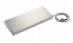
| AIR-ANT3213 | Diversity Omnidirectional | Pillar-mount diversity, indoor antenna with two RP-TNC connectors-Cosmetic antenna is ideal for the retail or hospital environment. Includes 36 in. of white RG-58 cable with a separation of coaxial cables that are joined together to form a 10 in. length. Has a tan cloth covering in a 12 x 5 rectangle. Included are two mounting brackets that will keep the antenna 6 in. off the wall. | |
| AIR-ANT2460P-R | Patch | Wall mount, indoor/outdoor directional patch antenna. Designed for use with any radio that features an RP-TNC antenna connector. For use in the 2400-2500 MHz frequency band. The pigtail cable is plenum rated, 36" long. | 6 dBi |
| AIR-ANT2465P-R | Diversity Patch | Wall-mount indoor/outdoor antenna with two RP-TNC connectors-Similar to the above patch, but providing diversity antennas in the same package for areas where multipath problems exist. The pigtail cable is plenum rated and 36" long. | 6.5 dBi |
| AIR-ANT2485P-R | Patch | Wall mount indoor/outdoor antenna with a RP-TNC connector-Designed for use with any radio that features a RP-TNC connector. For use in the 2400-2500 MHz frequency band. The plenum rated pigtail cable is 36" long. | 8.5 dBi |
| AIR-ANT24120 | Omnidirectional | Mast mount outdoor high gain antenna with a RP-TNC connector-This antenna was designed for WLAN applications for frequencies of 2400-2500 MHz. The antenna is omni directional and has a nominal gain of 12 dBi. This design uses an elevated center-feed to produce an elevation pattern with very little "squint" or beam-tilt. It is designed to be mounted on a round mast. | 12 dBi |
| AIR-ANT1729 | Patch | Wall mount, indoor/outdoor directional patch antenna. Designed for use with any radio that features an RP-TNC antenna connector. For use in the 2400-2500 MHz frequency band. The pigtail cable is 30" long. | 6 dBi |
| AIR-ANT2012 | Diversity Patch | Wall-mount indoor/outdoor antenna with two RP-TNC connectors-Similar to the above patch, but providing diversity antennas in the same package for areas where multipath problems exist. | 6 dBi |
| AIR-ANT2410Y-R | Yagi | High-gain outdoor directional antenna with a RP-TNC connector-This WLAN antenna is a completely enclosed yagi. It is designed to be used as a bridge antenna between two networks or for point-to-point communications. It has a nominal VSWR of 1.5:1 and is less than 2:1 over the entire frequency band. The gain is 10 dBi and the half-power beamwidth is 55 degrees. This antenna is normally mounted on a mast and is vertically polarized. | 10 dBi |
| Integrated BR1310G Patch Antenna | Patch | 2402-2497 MHz Patch Array Antenna. When the captured antenna version is ordered, this antenna is attached to the 1300 AP/Bridge and provides an integrated solution with exceptional gain. This antenna can not be removed for use with other radios. | 13 dBi |
| Integrated AP1120 Antenna | Omni | Diversity antenna package for 2.4 GHz designed for high performance in ceiling, wall and cubicle mount applications. Antennas provide omnidirectional coverage and can not be removed from the Access Point. No connectors are offered for additional external antennnas. | |
| AIR-ANT1949 | Yagi | High-gain outdoor directional antenna with a RP-TNC connector-This WLAN antenna is a completely enclosed 16-element yagi. It is designed to be used as a bridge antenna between two networks or for point-to-point communications. It has a nominal VSWR of 1.5:1 and is less than 2:1 over the entire frequency band. The gain is 13.5 dBi and the half-power beamwidth is 30 degrees. This antenna is normally mounted on a mast and is vertically polarized. | |
| AIR-ANT2414S-R | Sector | Mast mount outdoor sector antenna with a RP-TNC connector-This antenna was designed for WLAN applications for frequencies of 2400-2500 MHz. The antenna is directional and has a nominal gain of 14 dBi. Its flexible mounting bracket allows for either mast or wall mounting options. | 14 dBi |
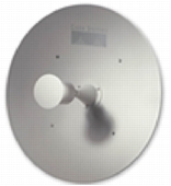
| AIR-ANT3338 | Dish | Very high-gain outdoor antenna with a RP-TNC connector-This WLAN antenna is a parabolic dish designed to be used as a bridge antenna between two networks or for point-to-point communications. It consists of an aluminum parabolic reflector and feed antenna. The antenna features a rugged mount. It also offers 20 degree fine adjustment for both horizontal and vertical planes. The antenna is provided with hardware for mast mounting. | 21 dBi |
Table 7. 5 GHz Antennas
| Cisco Part Number | Antenna Type | Description | Gain |
|---|---|---|---|
| Integrated RM21A Antenna | Omnidirectional/Patch | This articulating antenna is a dual function, diversity omni or patch antenna. It is permanently attached to the RM-21A 5 GHz Cardbus radio module used with the 1200 Series access point and operates between 5150-5825 MHz. When folded flat to the AP housing, it is in a 9 dBi patch mode, and when moved to any other position, it switches to a 5 dBi omni mode. In both cases it provides diversity antenna performance. | |
| AIR-ANT5135D-R | Omnidirectional | Indoor-only black dipole like omnidirectional antenna for 5 GHz. Used with the 802.11a radio (AIR-RM22A) and the 1200 Series access point. | 3.5 dBi |
| AIR-ANT5135DW-R | Omnidirectional | Indoor-only white dipole like omnidirectional antenna for 5 GHz. Used with the 802.11a radio (AIR-RM22A) and the 1200 Series access point. | 3.5 dBi |
| AIR-ANT5145V-R | Diversity Omnidirectional | Indoor-only diversity omnidirectional 5 GHz antenna for use with the 1200 Series and the 802.11a module (AIR-RM22A). | 4.5 dBi |
| AIR-ANT5160V-R | Omnidirectional | Indoor or outdoor use omnidirectional 5 GHz antenna for use with the 1200 Series and the 802.11a module (AIR-RM22A). Can be mast or ceiling mounted. | 6 dBi |
| AIR-ANT5170P-R | Diversity Patch | Wall Mount diversity patch antenna with RP-TNC Connectors-Designed for use in both indoor and outdoor applications. It comes with wall mount hardware, and has a gain of 7 dBi. It has a plenum rated pigtail cable of 36". | 7 dBi |
| AIR-ANT5195P-R | Patch | Wall or Mast Mount patch antenna-Designed for use indoor or outdoors, this antenna comes with both wall mount and articulating mast mount hardware. It has a plenum rated pigtail cable of 36". | 9.5 dBi |
| 2.4 GHZ AND 5 GHZ ACCESS POINT AND BRIDGE ANTENNAS WITH N TYPE CONNECTORS | |||
| AIR-ANT58G9VOA-N | Omnidirectional | An omnidirectional antenna, for use with the Cisco Aironet 1400 Series Wireless Bridge. This non-diversity, vertically polarized antenna operates in the UNII-3 band (5725 to 5825 MHz). The antenna is designed to be mast mounted in an outdoor environment. The antenna is not compatible with other Cisco Aironet radio products operating in the 5 GHz frequency band. | 9 dBi |
| AIR-ANT58G10SSA-N | Sector | A sector antenna for use with the Cisco Aironet 1400 Series Wireless Bridge. This non-diversity symmetric antenna operates in the UNII-3 band (5725-5825 MHz). The antenna is designed to be mounted outdoors on a mast or a suitable vertical surface. The antenna is not compatible with other Cisco Aironet radio products operating in the 5 GHz frequency band. | 9.5 dBi |
| Integrated BR1410 Patch Antenna | Integrated Patch | 5.8 GHz UNII-3 Patch antenna. When the captured antenna version is ordered, this antenna is attached to the BR1410 bridge and provides for an integrated solution with exceptional gain. The antenna is not compatible with other Cisco Aironet radio products operating in the 5 GHz frequency band. | |
| AIR-ANT58G28SDA-N | Dish | A parabolic dish antenna for use with the Cisco Aironet 1400 Series Wireless Bridge. This non-diversity parabolic antenna operates in the UNII-3 band (5725-5825 MHz). The antenna is designed to be mounted outdoors on a mast. The antenna is designed to be used at the hub or client site of a point-to-point installation, or point-to-multipoint client sites, providing extended range. The antenna is not compatible with other Cisco Aironet radio products operating in the 5 GHz frequency band. | 28 dBi |
| AIR-ANT5175V-N | Omni | A 7.5 dBi antenna which supports 4900-5825 MHz. It has a 12" pigtail cable and a N-type connector. | 7.5 dBi |
| AIR-ANT2455V-N | Omni | A 5.5 dBi antenna for use in the 2400-2484 MHz frequency band which utilizes a N-type connector. This antenna directly mounts onto the unit, and has no cable attachments. | 5.5 dBi |
Table 8. 2.4 GHz and 5 GHz Access Point Integrated Antennas
| Cisco Part Number | Antenna Type | Description | Gain |
|---|---|---|---|
| Integrated AP1130AG Antenna | Omni | Diversity antenna package for both 2.4 GHz and 5 GHz designed for high performance in both ceiling and wall mount applications. Antennas provide hemispherical coverage and can not be removed from the Access Point. No connectors are offered for additional external antennnas. | 5 GHz: 4.5 dBi |
| Integrated AP1000 Antenna | Bi-Directional | 2.4 GHz offers diversity patch antennas to provide bi-directional while 5 GHz is a bi-directional antenna. The AP can be mounted on the ceiling or in wall mount applications. The AP1010 offers integrated antennas only, while the AP1020 and AP1030 offers both integrated antennas and (2) RP-TNC, 2.4 GHz connectors and (1) 5 GHz RP-TNC connector. | 5 Ghz: 5 dBi |
CISCO AIRONET CABLE DESCRIPTIONS
Table 9 below defines the cables available for interconnecting the antennas and the radio devices for the Cisco Aironet product line.Table 9. Cisco Cables
| Cisco Part Number | Type of Cable | Description | Loss (2.4 GHz) |
|---|---|---|---|
| AIR-CAB020LL-R | Interconnect | 20 ft. low-loss cable with RP-TNC connectors | 1.3 dB |
| AIR-CAB050LL-R | Interconnect | 50 ft. low-loss cable with RP-TNC connectors | 3.4 dB |
| AIR-CAB100ULL-R | Interconnect | 100 ft. ultra-low-loss cable with RP-TNC connectors | 4.4 dB |
| AIR-CAB150ULL-R | Interconnect | 150 ft. ultra-low-loss cable with RP-TNC connectors | 6.6 dB |
| AIR-420-002537-060 | Bulkhead Extender | 60" RG58 type cable with RP-TNC connectors | 2 dB |
Table 10. Accessories
| Cisco Part Number | Name | Description |
|---|---|---|
| AIR-ACC2662 | Yagi Articulating Mount | This mount permits the Yagi antenna to be mounted to a flat surface or a mast, and then be adjusted in both horizontal and vertical angles. |
| AIR-ACC245LA-R | Lightning Arrestor | Supports both 2.4 GHz and 5 GHz operation. Provides lightning and related energy surges at the antenna from reaching the radio circuitry. A ground ring is included. |
CISCO AIRONET ANTENNA SPECIFICATIONS
The following section provides detailed descriptions, including physical and electrical specifications for the antennas offered by Cisco for the CiscoAironet product line.2.0 dBi CEILING MOUNT DIVERSITY PATCH
AIR-ANT5959
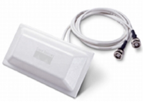
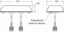 |
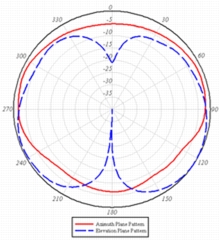 |
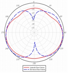 |
| Dimensions and Mounting Specifications | Left Antenna Patterns | Right Antenna Pattern |
| Frequency Range | 2.4-2.5 GHz | |
| VSWR | 1.7:1 | |
| Power | 5 watts | |
| Gain | 2.0 dBi | |
| Polarization | Vertical linear | |
| Azimuth 3dB BW | Omnidirectional | |
| Elevations 3dB BW | 80 degrees | |
| Antenna Connector | RP-TNC | |
| Dimensions (H x W x D) | 5.3 x 2.8 x 0.9 in. | |
| Mounting | Drop ceiling cross member mount | |
2.2 dBi POS DIVERSITY DIPOLE (FOR USE WITH LMC CARDS)
AIR-ANT3351
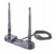
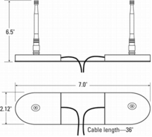 |
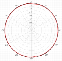 |
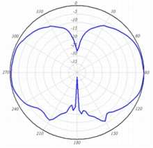 |
| Dimensions and Mounting Specifications | Azimuth Plane Radiation Pattern | Elevation Plane Radiation Pattern |
| Frequency Range | 2.4-2.483 GHz | |
| VSWR | Less than 2:1 | |
| Gain | 2.2 dBi | |
| Polarization | Linear | |
| Azimuth 3dB BW | Omnidirectional | |
| Elevations 3dB BW | 70 degrees | |
| Antenna Connector | MMCX (2) | |
| Dimensions (H x W x D) | 6.5 x 7.0 x 2.12 in. | |
2 dBi DIPOLE
AIR-ANT4941
 |
 |
 |
|
| Dimensions and Mounting Specifications | Azimuth Plane Radiation Pattern | Elevation Plane Radiation Pattern | |
| Frequency Range | 2.4-2.484 GHz | ||
| VSWR | Less than 2:1 | ||
| Power | 5 watts | ||
| Gain | 2 dBi | ||
| Polarization | Linear | ||
| Azimuth 3dB BW | Omnidirectional | ||
| Elevations 3dB BW | 70 degrees | ||
| Antenna Connector | RP-TNC | ||
| Dimensions (H) | 4.5 in. | ||
| Mounting | To RP-TNC Connector | ||
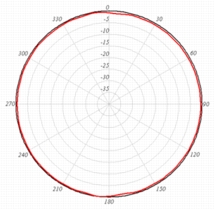
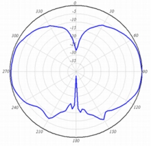
2 dBi DIPOLE
AIR-ANT2422DW-R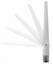
 |
 |
 |
|
| Dimensions and Mounting Specifications | Azimuth Plane Radiation Pattern | Elevation Plane Radiation Pattern | |
| Frequency Range | 2.4-2.484 GHz | ||
| VSWR | Less than 2:1 | ||
| Power | 5 watts | ||
| Gain | 2 dBi | ||
| Polarization | Linear | ||
| Azimuth 3dB BW | Omnidirectional | ||
| Elevations 3dB BW | 70 degrees | ||
| Antenna Connector | RP-TNC | ||
| Dimensions (H) | 4.5 in. | ||
| Mounting | To RP-TNC Connector | ||
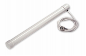
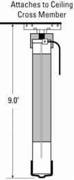
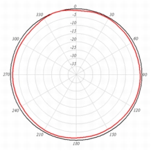
5.2 dBi CEILING MOUNT OMNIDIRECTIONAL
AIR-ANT1728
 |
 |
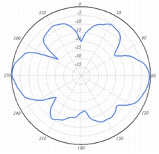 |
| Dimensions and Mounting Specifications | Azimuth Plane Radiation Pattern | Elevation Plane Radiation Pattern |
| Frequency Range | 2.4-2.83 GHz | |
| VSWR | Less than 2:1, 1.5:1 Nominal | |
| Gain | 5.2 dBi | |
| Polarization | Vertical | |
| Azimuth 3dB BW | Omnidirectional 360 degrees | |
| Elevations Plan (3dB BW) | 36 degrees | |
| Antenna Connector | RP-TNC | |
| Dimensions (H x W) | 9 x 1.25 in. | |
| Mounting | Drop ceiling cross member-indoor only | |
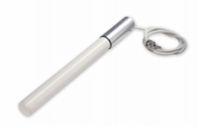
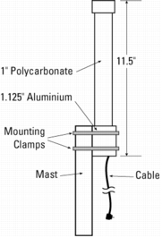
5.2 dBi MAST MOUNT OMNIDIRECTIONAL
AIR-ANT2506
 |
 |
 |
| Dimensions and Mounting Specifications | Azimuth Plane Radiation Pattern | Elevation Plane Radiation Pattern |
| Frequency Range | 2.4-2.83 GHz | |
| VSWR | Less than 2:1, 1.5:1 Nominal | |
| Gain | 5.2 dBi | |
| Polarization | Vertical | |
| Azimuth 3dB BW | Omnidirectional 360 degrees | |
| Elevations Plan (3dB BW) | 36 degrees | |
| Antenna Connector | RP-TNC | |
| Dimensions (H x W) | 11.5 x 1.125 in. | |
| Mounting | Mast mount-indoor/outdoor | |
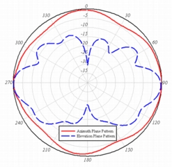
5.2 dBi PILLAR MOUNT DIVERSITY OMNIDIRECTIONAL
AIR-ANT3213
 |
 |
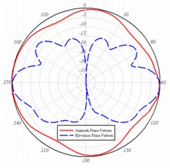 |
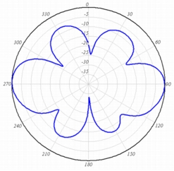
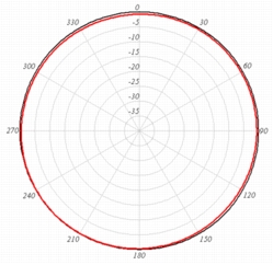
| Dimensions and Mounting Specifications | Left Antenna Radiation Patterns | Right Antenna Radiation Patterns |
| Frequency Range | 2.4-2.83 GHz | |
| VSWR | 2:1 Nominal | |
| Gain | 5.2 dBi | |
| Polarization | Vertical | |
| Azimuth 3dB BW | Omnidirectional 360 degrees | |
| Elevation 3dB BW | 25 degrees | |
| Antenna Connector | RP-TNC | |
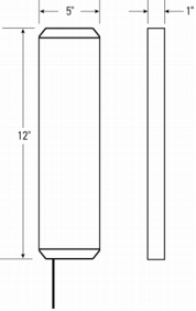
| Dimensions (H x W x D) | 12 x 5 x 1 in. | |
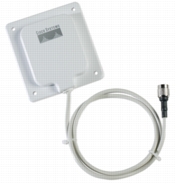
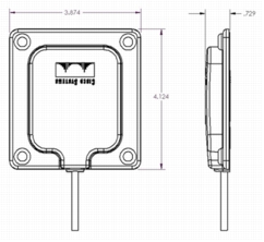
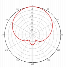
6 dBi WALL MOUNT DIRECTIONAL
AIR-ANT2460P-R
 |
 |
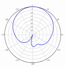 |
| Dimensions and Mounting Specifications | Azimuth Plane Radiation Pattern | Elevation Plane Radiation Pattern |
| Frequency Range | 2.4-2.5 GHz | |
| VSWR | Less than 2:1 | |
| Gain | 6 dBi | |
| Polarization | Vertical | |
| Azimuth 3dB BW | 75 degrees | |
| Elevation Plan (3dB BW) | 73 degrees | |
| Antenna Connector | RP-TNC | |
| Dimensions (H x W x D) | 4.1 x 3.9 x .9 in. | |
| Mounting | Wall Mount | |
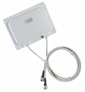
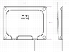
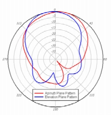
6.5 dBi WALL MOUNT
AIR-ANT2465
 |
 |
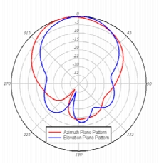 |
| Dimensions and Mounting Specifications | Left Antenna Radiation Patterns | Right Antenna Radiation Patterns |
| Frequency Range | 2.4-2.5 GHz | |
| VSWR | 1.7:1 Nominal | |
| Gain | 6.5 dBi | |
| Polarization | Vertical | |
| Azimuth 3dB BW | 75 degrees | |
| Elevations Plan (3dB BW) | 57 degrees | |
| Antenna Connector | RP-TNC | |
| Dimensions (H x W x D) | 5 x 6.7 x .1 in. | |
| Mounting | Wall Mount | |
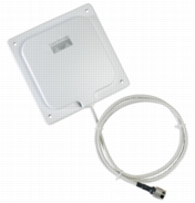
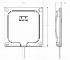
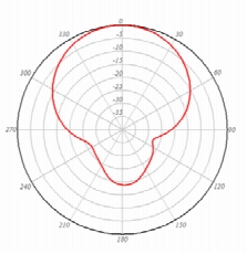
8.5 dBi WALL MOUNT
AIR-ANT2485P-R
 |
 |
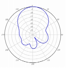 |
| Dimensions and Mounting Specifications | Azimuth Plane Radiation Pattern | Elevation Plane Radiation Pattern |
| Frequency Range | 2.4-2.5 GHz | |
| VSWR | 2:1 Max, 1.5:1 Nominal | |
| Gain | 8.5 dBi | |
| Polarization | Vertical | |
| Azimuth 3dB BW | 66 degrees | |
| Elevations 3dB BW | 56 degrees | |
| Antenna Connector | RP-TNC | |
| Dimensions (H x W x D) | 5.3 x 5.3 x .75 in. | |
| Mounting | Wall Mount | |
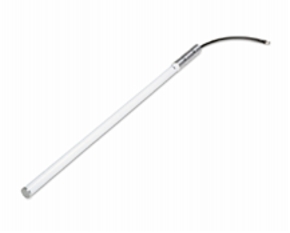
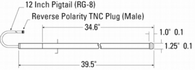
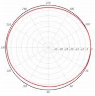
12 dBi MAST MOUNT OMNIDIRECTIONAL
AIR-ANT24120
 |
 |
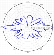 |
| Dimensions and Mounting Specifications | Azimuth Plane Radiation Pattern | Elevation Plane Radiation Pattern |
| Frequency Range | 2400-2500 MHz | |
| VSWR | 1.5:1 | |
| Gain | 12 dBi | |
| Polarization | Linear, Vertical | |
| Azimuth 3dB BW | Omnidirectional 360 degrees | |
| Elevation (3dB BW) | 7 degrees | |
| Antenna Connector | RP-TNC | |
| Dimensions (H x W) | 42 x 1.25 in. | |
| Wind Rating | 125 MPH | |
| Mounting | Mast Mount | |
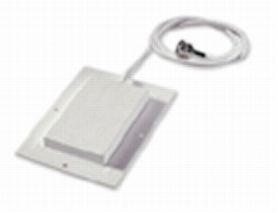
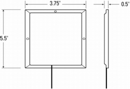
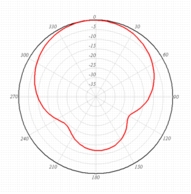
6 dBi WALL MOUNT PATCH
AIR-ANT1729
 |
 |
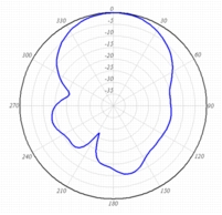 |
| Dimensions and Mounting Specifications | Azimuth Plane Radiation Pattern | Elevation Plane Radiation Pattern |
| Frequency Range | 2.4-2.5 GHz | |
| VSWR | Less than 2:1 | |
| Gain | 6 dBi | |
| Polarization | Linear | |
| Azimuth 3dB BW | 65 degrees | |
| Elevations Plan (3dB BW) | 70 degrees | |
| Antenna Connector | RP-TNC | |
| Dimensions (H x W x D) | 5.5 x 3.75 x 0.5 in. | |
| Mounting | Wall Mount | |
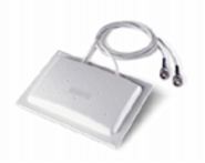
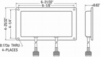
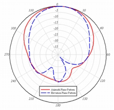
6 dBi WALL MOUNT DIVERSITY PATCH
AIR-ANT2012
 |
 |
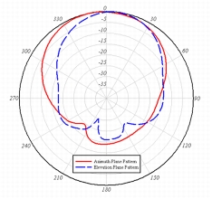 |
| Dimensions and Mounting Specifications | Left Antenna Patterns | Right Antenna Patterns |
| Frequency Range | 2.4-2.5 GHz | |
| VSWR | 1.7:1 Nominal | |
| Gain | 6 dBi | |
| Polarization | Vertical | |
| Azimuth 3dB BW | 80 degrees | |
| Elevations Plan (3dB BW) | 55 degrees | |
| Antenna Connector | RP-TNC | |
| Dimensions (H x W x D) | 6.65 x 4.78 x .82 in. | |
| Mounting | Wall Mount | |
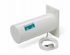
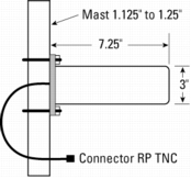
10 dBi WALL/MAST MOUNT YAGI
AIR-ANT2410Y-R
 |
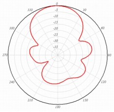 |
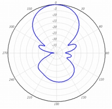 |
| Dimensions and Mounting Specifications | Azimuth Plane Radiation Pattern | Elevation Plane Radiation Pattern |
| Frequency Range | 2.4-2.483 GHz | |
| VSWR | Less than 2:1 | |
| Gain | 10 dBi | |
| Polarization | Vertical | |
| Azimuth 3dB BW | 55 degrees | |
| Elevations Plan 3dB BW | 40 degrees | |
| Antenna Connector | RP-TNC | |
| Dimensions (H x W) | 3 x 7.25 in. | |
| Mounting | Wall/Mast Mount | |
Cisco Aironet 1300 Series Integrated Antenna
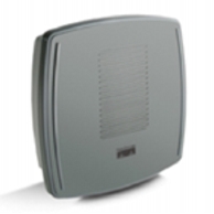
Azimuth Plane Radiation Pattern 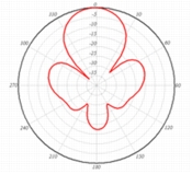 |
Elevation Plane Radiation Pattern 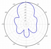 |
| Frequency Range | 2.4-2.83 GHz |
| Antenna Type | 2 x 2 Patch Array |
| Front to Back Gain | 13 dBi |
| Polarization | Linear Vertical |
| VSWR | 1.5:1 VSWR Nominal |
| E-Plane 3 dB Beamwidth | 36 degrees |
| H-Plane 3 dB Beamwidth | 38 degrees |
Cisco Aironet 1100 Series Integrated Antenna
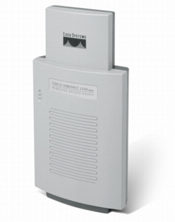
Azimuth Plane Radiation Pattern 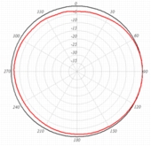 |
Elevation Plane Radiation Pattern 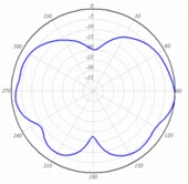 |
| Frequency Range | 2.4-2.5GHz |
| Gain | 2 dBi |
| Polarization | Linear |
| Azimuth 3dB BW | Omni |
| Elevations 3dB BW | 50 degrees |
| Antenna Connector | Integrated |
| Mounting | Integrated |
| Antenna Type | Omni |
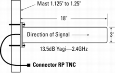
13.5 dBi MAST/WALL MOUNT YAGI
AIR-ANT1949
 |
 |
 |
| Dimensions and Mounting Specifications | Azimuth Plane Radiation Pattern | Elevation Plane Radiation Pattern |
| Frequency Range | 2.4-2.83 GHz | |
| VSWR | Less than 2:1, 1.5:1 Nominal | |
| Gain | 13.5 dBi | |
| Front to Back Ratio | Greater than 30 dB | |
| Polarization | Vertical | |
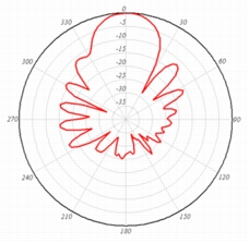
| Azimuth 3dB BW | 30 degrees | |
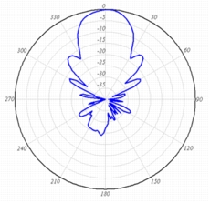
| Elevations 3dB BW | 25 degrees | |
| Antenna Connector | RP-TNC | |
| Dimensions (H x W) | 18 x 3 in. | |
| Wind Rating | 110 MPH | |
| Mounting | Mast/Wall Mount | |
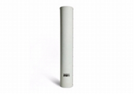
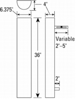
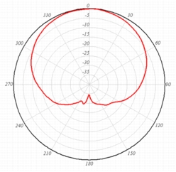
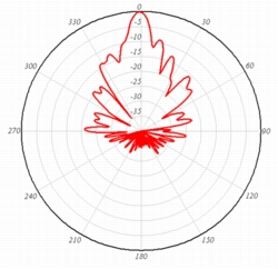
14 dBi MAST MOUNT SECTOR
AIR-ANT2414S-R
 |
 |
 |
| Dimensions and Mounting Specifications | Azimuth Plane Radiation Pattern | Elevation Plane Radiation Pattern |
| Frequency Range | 2.4-2.5 GHz | |
| VSWR | 1.5:1 | |
| Gain | 14 dBi | |
| Polarization | Linear, Vertical | |
| Azimuth 3dB BW | 90 degrees | |
| Elevations 3dB BW | 8.5 degrees | |
| Antenna Connector | RP-TNC | |
| Dimensions (H x W x D) | 36 x 6 x 4 in. | |
| Mounting | Mast Mount | |
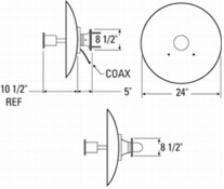
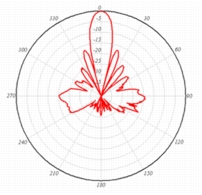
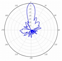
21 dBi MAST MOUNT PARABOLIC DISH
AIR-ANT3338
 |
 |
 |
| Dimensions and Mounting Specifications | Azimuth Plane Radiation Pattern | Elevation Plane Radiation Pattern |
| Frequency Range | 2.4-2.83 GHz | |
| VSWR | Less than 1.8:1, 15:1 Nominal | |
| Power | 5 watts | |
| Gain | 21 dBi | |
| Front to Back Ratio | Greater than 25 dB | |
| Maximum Side Lobe | -17 dB | |
| Polarization | Vertical | |
| Azimuth 3dB BW | 12 degrees | |
| Elevation 3dB BW | 12 degrees | |
| Antenna Connector | RP-TNC | |
| Dimensions (H x W) | 24 x 15.5 in. | |
| Wind Rating | 110 MPH | |
| Mounting | Mast Mount | |
9 dBi PATCH/5 dBi OMNIDIRECTIONAL
Integrated Antenna-Part of AP1200 5-GHz Radio Module (Part Number AIR-RM21A)
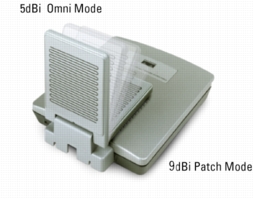
5 dBi Omni Mode Azimuth Plane Radiation Pattern 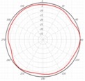 |
9 dBi Patch Mode Azimuth Plane Radiation Pattern 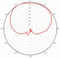 |
5 dBi Omni Mode Elevation Plane Radiation Pattern 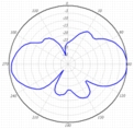 |
9 dBi Patch Mode Elevation Plane Radiation Pattern 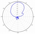 |
| Frequency Range | 5.15-5.35 GHz |
| VSWR | 1.5:1 Nominal |
| Gain | 5 dBi Omnidirectional 9 dBi Patch |
| Polarization | Vertical |
| Omni-Directional Azimuth Plane-5 dBi | 360 degrees |
| Omni-Directional Elevation Plane-5 dBi | 36 degrees |
| Patch Azimuth Plane-9 dBi | 100 degrees |
| Patch Elevation Plane-9 dBi | 45 degrees |
| Antenna Connector | Integrated-none available |
3.5 dBi DIPOLE
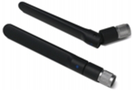
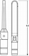
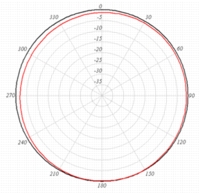
AIR-ANT5135D-R
 |
 |
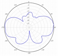 |
| Dimensions and Mounting Specifications | Azimuth Plane Radiation Pattern | Elevation Plane Radiation Pattern |
| Frequency Range | 5.15-5.85 GHz | |
| VSWR | 2:1 or better | |
| Gain | 3.5 dBi | |
| Polarization | Linear | |
| Azimuth 3dB BW | Omnidirectional | |
| Elevations 3dB BW | 40 degrees | |
| Antenna Connector | RP-TNC | |
| Dimensions (H) | 5.3 in. | |
| Mounting | RP-TNC Connector | |
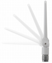
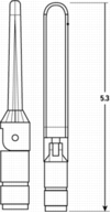
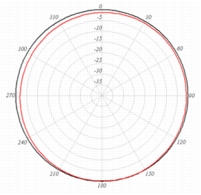
3.5 dBi DIPOLE
AIR-ANT5135DW-R
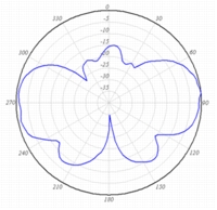
 |
 |
 |
| Dimensions and Mounting Specifications | Azimuth Plane Radiation Pattern | Elevation Plane Radiation Pattern |
| Frequency Range | 5.15-5.85 GHz | |
| VSWR | 2:1 or better | |
| Gain | 3.5 dBi | |
| Polarization | Linear | |
| Azimuth 3dB BW | Omnidirectional | |
| Elevations 3dB BW | 40 degrees | |
| Antenna Connector | RP-TNC | |
| Dimensions (H) | 5.3 in. | |
| Mounting | RP-TNC Connector | |
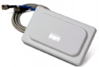
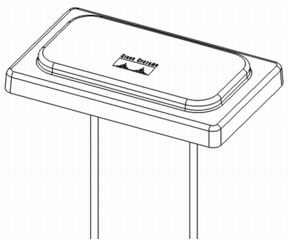
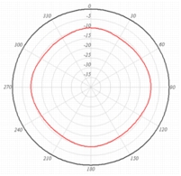
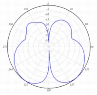
4.5 dBi DIVERSITY OMNIDIRECTIONAL
AIR-ANT5145V-R
 |
 |
 |
|
| Dimensions and Mounting Specifications | Azimuth Plane Radiation Pattern | Elevation Plane Radiation Pattern | |
| Frequency Range | 5.15-5.85 GHz | ||
| VSWR | 2:1 or better | ||
| Gain | 4.5 dBi | ||
| Polarization | Linear | ||
| Azimuth 3dB BW | Diversity Omnidirectional | ||
| Elevations 3dB BW | 50 degrees | ||
| Antenna Connector | RP-TNC | ||
| Dimensions (H x W x D) | 6.75 x 4.1 x 1 in. | ||
| Mounting | Drop ceiling cross member mount | ||
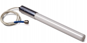
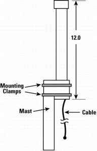
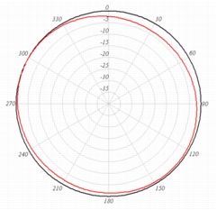
6 dBi OMNIDIRECTIONAL
AIR-ANT5160V-R
 |
 |
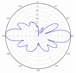 |
| Dimensions and Mounting Specifications | Azimuth Plane Radiation Pattern | Elevation Plane Radiation Pattern |
| Frequency Range | 5.15-5.85 GHz | |
| VSWR | 2:1 or better | |
| Gain | 6 dBi | |
| Polarization | Vertical | |
| Azimuth 3dB BW | Omnidirectional 360 degrees | |
| Elevation 3dB BW | 17 degrees | |
| Antenna Connector | RP-TNC | |
| Dimensions (H x W x D) | 12 x 1 in. | |
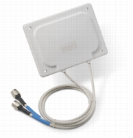
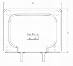
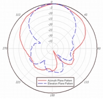
7 dBi DIVERSITY PATCH WALL MOUNT
AIR-ANT5170P-R
 |
 |
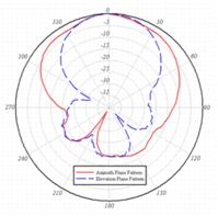 |
| Dimensions and Mounting Specifications | Left Antenna Radiation Pattern | Right Antenna Radiation Pattern |
| Frequency Range | 5.1-5.8 GHz | |
| VSWR | 2:1 or better | |
| Gain | 7 dBi | |
| Polarization | Linear and vertical | |
| Azimuth Plane | 70 degrees | |
| Elevation Plane | 50 degrees | |
| Connectors | RP-TNC | |
| Dimensions (H x W x D) | 14.5 cm x 10.9 cm x 1.8 cm | |
| Mounting | Wall mount | |
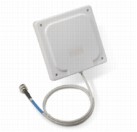
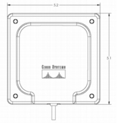
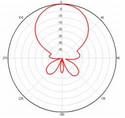
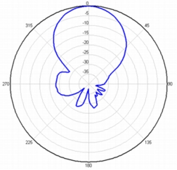
9.5 dBi PATCH WALL OR ARTICULATING MAST MOUNT
AIR-ANT5195P-R
 |
 |
 |
| Dimensions and Mounting Specifications | Azimuth Plane Radiation Pattern | Elevation Plane Radiation Pattern |
| Frequency Range | 5.1-5.8 GHz | |
| VSWR | 2:1 or better | |
| Gain | 9.5 dBi | |
| Polarization | Linear and vertical | |
| Azimuth Plane | 50 degrees | |
| Elevation Plane | 43 degrees | |
| Connectors | RP-TNC | |
| Dimensions (H x W x D) | 12.9 cm x 12.9 cm x 2.5 cm | |
| Mounting | Wall mount or articulating mast mount | |
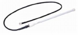
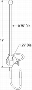
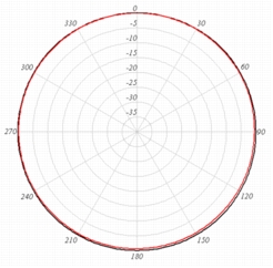
9 dBi MAST MOUNT OMNIDIRECTIONAL
AIR-ANT58G9VOA-N
 |
 |
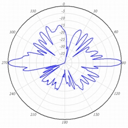 |
| Dimensions and Mounting Specifications | Azimuth Plane Radiation Pattern | Elevation Plane Radiation Pattern |
| Frequency Range | 5.725-5.825 GHz | |
| Antenna Connector | N-Male | |
| VSWR | 1.5:1 Nominal | |
| Maximum Power | 4 watts | |
| Gain | 9 dBi | |
| Polarization | Vertical | |
| Dimensions | 17 x 1.25 in. | |
| Mounting | 1.5-2.5 in. Mast mount | |
| Azimuth 3dB BW | Omnidirectional | |
| Wind Speed (operational) | 100 MPH | |
| Elevations Plan (3dB BW) | 6 degrees | |
| Wind Speed (survival) | 125 MPH | |
| Beamtilt | 0 degrees | |
9.5 dBi MAST MOUNT SECTOR
AIR-ANT58G10SSA-N
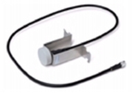
|
Dimensions and Mounting Specifications 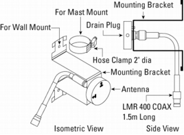 |
Azimuth Plane Radiation Pattern 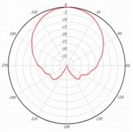 |
Elevation Plane Radiation Pattern 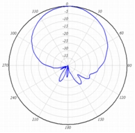 |
||
| Frequency Range | 5.725-5.825 GHz | Antenna Connector | N-Male | |
| VSWR | 1.5:1 Nominal | Maximum Power | 4 watts | |
| Gain | 9.5 dBi | Temperature (operating | -20°F Min, +60°C Max | |
| Polarization | H or V | Mounting | 1.5-2.5 in. Mast mount | |
| Azimuth 3dB BW | 60 degrees | Wind Speed (operational) | 100 MPH | |
| Elevations Plan (3dB BW) | 60 degrees | Wind Speed (survival) | 125 MPH | |
28 dBi MAST MOUNT DISH-5.8 GHZ
AIR-ANT58G28SDA-N
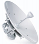
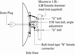 |
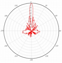 |
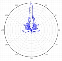 |
| Dimensions and Mounting Specifications | Azimuth Plane Radiation Pattern | Elevation Plane Radiation Pattern |
| Frequency Range | 5.725-5.825 GHz | |
| Wind Speed (survival) | 125 MPH | |
| VSWR | 1.5:1 Nominal | |
| Antenna Connector | N-Male | |
| Gain | 28 dBi | |
| Maximum Power | 4 watts | |
| Polarization | V or H | |
| Azimuth 3dB BW | 4.75 degrees | |
| Mounting | 1.5-2.5 in. Mast mount | |
| Elevations Plan (3dB BW) | 4.75 degrees | |
| Wind Speed (operational) | 100 MPH | |
| Dimensions | 24 in. Diameter | |
7.5 dBi OMNIDIRECTIONAL
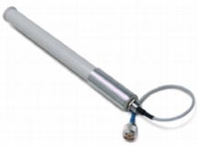
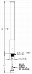
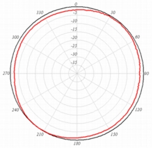
AIR-ANT5175V-N
 |
 |
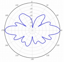 |
| Dimensions and Mounting Specifications | Azimuth Plane Radiation Pattern | Elevation Plane Radiation Pattern |
| Frequency Range | 4.9-5.8 GHz | |
| VSWR | 2:1 or better | |
| Gain | 7.5 dBi for 5GHz bands. 6 dBi for 4.9GHz bands. | |
| Polarization | Linear | |
| Azimuth Plane | Omnidirectional | |
| Elevation Plane | 50 degrees | |
| Connectors | N | |
| Dimensions (H x W x D) | 31.75 cm x 2.54 cm | |
| Mounting | Direct mount | |
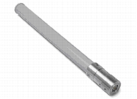
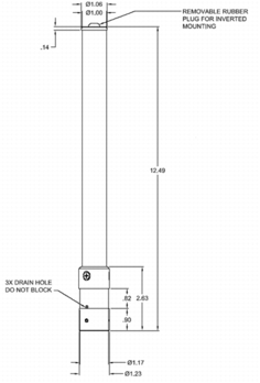
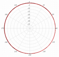
5.5 dBi OMNIDIRECTIONAL
AIR-ANT2455V-N
 |
 |
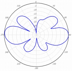 |
| Dimensions and Mounting Specifications | Azimuth Plane Radiation Pattern | Elevation Plane Radiation Pattern |
| Frequency Range | 2.4-2.83 GHz | |
| VSWR | 2:1 or better | |
| Gain | 5.5 dBi | |
| Polarization | Linear | |
| Azimuth Plane | Omnidirectional | |
| Elevation Plane | 25 degrees | |
| Connectors | N | |
| Dimensions (H x W x D) | 30.48 cm x 2.54 cm | |
| Mounting | Direct mount | |
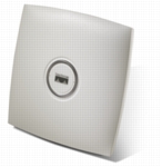
CISCO AIRONET 1130 SERIES INTEGRATED ANTENNA
2.4 GHz, 3 dBi Azimuth Plane Radiation Pattern  |
5 GHz, 4.5 dBi Azimuth Plane Radiation Pattern  |
2.4 GHz, 3 dBi Elevation Plane Radiation Pattern
|
5 GHz, 4.5 dBi Elevation Plane Radiation Pattern
|
|
| Frequency Range | 2.4-2.5GHz5.15-5.8 GHz | |||
| Gain | 2.4 GHz: 3 dBi5 GHz: 4.5 dBi | |||
| Polarization | Linear, Vertical | |||
| Azimuth 3dB BW | Omnidirectional | |||
| Elevations 3dB BW | 50 degrees | |||
| Antenna Connector | Integrated | |||
| Mounting | Integrated | |||
| Antenna Type | Omnidirectional | |||
CISCO AIRONET 1000 SERIES INTEGRATED ANTENNA
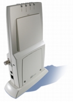
2.4 GHz, 6 dBi Azimuth Plane Radiation Pattern 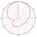 |
5 GHz, 5 dBi Azimuth Plane Radiation Pattern 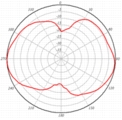 |
2.4 GHz,6 dBi Elevation Plane Radiation Pattern
|
5 GHz, 5 dBi Elevation Plane Radiation Pattern
|
|
| Frequency Range | 2.4-2.5GHz 5.15-5.8 GHz |
|||
|
Gain |
2.4 GHz: 6 dBi 5 GHz: 5 dBi |
|||
| Polarization | Linear, Vertical | |||
| Azimuth 3dB BW | 2.4 GHz: 70 degrees 5 GHz: 55 degrees |
|||
| Elevations 3dB BW | 2.4 GHz: 60 degrees 5 GHz: 35 degrees |
|||
| Antenna Connector | Integrated | |||
| Mounting | Integrated | |||
| Antenna Type | Bi-directional | |||


